Neben Lesbaren und einfachen Uhrzeiten hat sich jemand die Nato Zeit oder DateTimeGroup ausgedacht.
Das Format, welches z.b. für den 6.12.2024 12:34Uhr wie so aussieht: “ 061234ADec24″ wird auch im THW verwendet.
Daraus wurde in den letzten Tagen nun folgendes Projekt:

Machen wir mal eine schnelle Bauanleitung dafür. Was man benötigt:
- Pico W (leider noch nicht der picow 2) – (ca. 7,50 €)
- 3 Stück (4* 8×8 Dot Matrix LED Module mit max7219 chips) (ca. 7€ Stück)
- optional 1* RTC Modul / DS1307 oder DS3231 (Stück ca. 2,50€)
- Lötkolben und Heißkleber ( natürlich kann man auch ein Gehäuse dafür drucken)
- Instanz von Esphome . zum Beispiel in Homeassistant
Schritt für schritt Anleitung :
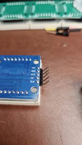
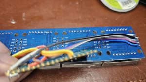
- Verbinden der Displays. Wichtig ist das man beachtet, wo der Dateneingang ist.
2. Die Eingangspins umbiegen und in die Ausgangs-Löcher einfädeln, dann verlöten.
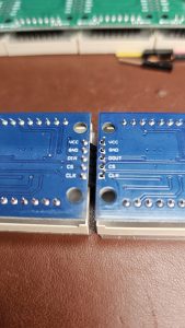

3. Das ganze mit dem dritten Modul wiederholen.
4. Kabel abisolieren und an die Eingangspins der Displaymodule Verlöten.
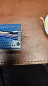
5. Die Kabel auf dem PicoW verlöten:
- VCC => Pin 40 => +5V
- GND => Pin 38 => GND
- D-IN => SPI0 TX => Pin5 / GPIO03
- CS => SPI0 CSn => Pin7 / GPIO05
- CLK => SPI0 SCK => Pin4 / GPIO02
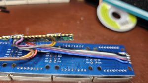
6. Optional: Realtime Clock anschließen und Verlöten:
- VCC => Pin 36 / 3.3V Out
- GND => Pin 28 / GND
- SDA => Pin 26 / I2C0 SDA / GPIO20
- SCL => Pin 27 / I2C0 SCL / GPIO21
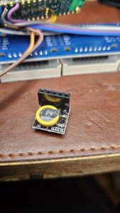
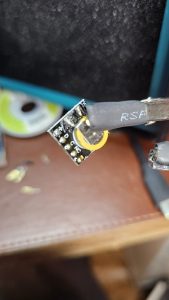
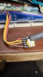
7. Schritt : alles mit Heisskleb an der Rückseite des Displays befestigen
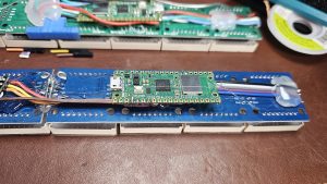
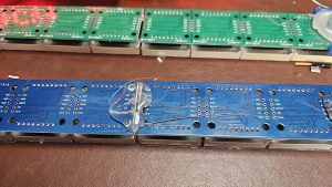
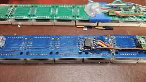
8. Software aufspielen:
die Software findest du hier : Lexorius/ESP-Home-DTG-Clock: ESP Home Project – with MAX7219 Digit Display
—————
esphome:
name: picow-clock-ds1307
friendly_name: PicoW-Clock-ds1307
on_boot:
then:
# read the RTC time once when the system boots
ds1307.read_time:rp2040:
board: rpipicow# Enable logging
logger:# Enable Home Assistant API
api:
encryption:
key: „<enc>“ota:
– platform: esphome
password: „<ota>“wifi:
ssid: !secret wifi_ssid
password: !secret wifi_password# Enable fallback hotspot in case wifi connection fails
ap:
ssid: „Picow-Clock-Ds1307“
password: „<recover>“i2c:
sda: 20
scl: 21
scan: true
id: mainbusspi:
clk_pin: GPIO02
mosi_pin: GPIO03#SPI0_SCK Pin 6
#SPI0_MOSI Pin 7
#SPI0_MISO Pin 4
#SPI1_SCK Pin 10
#SPI1_MOSI Pin 11
#SPI1_MISO Pin 8display:
– platform: max7219digit
update_interval: 1s
cs_pin: GPIO05
num_chips: 12
scroll_speed: 0ms
intensity: 7
lambda: |
auto time = id(sntp_time).now();// it.printf(0,0,id(digit_font),“%s“, id(Scrolltext).state.c_str());
if (time.is_valid()) {
if (time.is_dst ){if ((int(time.second) % 2) == 0){
it.strftime(0, 0, id(digit_font), „%d %H%M B %b %y.“, id(sntp_time).now());
} else {
it.strftime(0, 0, id(digit_font), „%d %H%M B %b %y“, id(sntp_time).now());
}} else {
if ((int(time.second) % 2) == 0){
it.strftime(0, 0, id(digit_font), „%d %H%M A %b %y.“, id(sntp_time).now());
} else {
it.strftime(0, 0, id(digit_font), „%d %H%M A %b %y“, id(sntp_time).now());
}}
} else {
if (id(wifisignal).has_state()) {
it.printf(0, 0, id(digit_font), „Getting Time from NTP“);
}
else {
it.printf(0, 0, id(digit_font),“Connecting Wifi“);
}
}font:
– file: „fonts/pixelmix.ttf“
id: digit_font
size: 8sensor:
– platform: wifi_signal
name: „WiFi Signal Sensor“
id: wifisignal
update_interval: 60stime:
– platform: sntp
id: sntp_time
timezone: Europe/Berlin
servers:
– 0.pool.ntp.org
– 1.pool.ntp.org
– 2.pool.ntp.org
on_time_sync:
then:
# … and update the RTC when the synchronization was successful
ds1307.write_time:– platform: ds1307
# repeated synchronization is not necessary unless the external RTC
# is much more accurate than the internal clock
update_interval: never
# instead try to synchronize via network repeatedly …
8. UF2 Datei von ESP Home auf den PicoW kopieren und PicoW neu starten.
Fertig.

